Panduit® PN22-2F-C
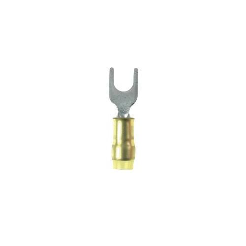
Panduit® Pan-Term® PN22-2F-C Standard Fork Terminal, #22 Conductor, 0.66 in L, Seamed/Insulation Grip Sleeve Barrel, Copper, Yellow
- Manufacturer Name: Panduit
- MPN: PN22-2F-C
- Brand Name: Panduit®
- UPC: 074983890309
- FEPN: PN22-2F-C PC
- Min Order Qty: 1
- Quantity Interval: 1
-
Inventory Availability

-
Retail Price:

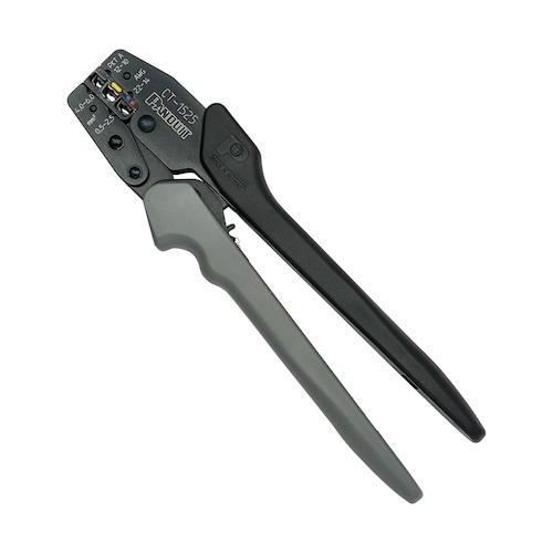
Panduit® Pan-Term® terminals are designed and manufactured for fast assembly and reliable performance. Panduit® provides an extensive line of tooling designed specifically to provide optimum performance. As the demand for loose piece terminals increases, it becomes essential to provide a complete system for termination products.
Panduit® Pan-Term® Fork Terminal, Standard, Series: PN-F, Copper/Solid/Stranded Conductor, #22 Conductor, #2 Stud, 0.66 in Length, Seamed/Insulation Grip Sleeve Barrel, Fork Tongue, 0.2 in W x 0.02 in THK Tongue, 600 V, Specifications: 7/32 in L Wire Strip, 0.09 in Dia Maximum Wire Insulation, 0.56 in Barrel to Hole Length, Nylon Insulated, Fork Shape Enclosure, 221 deg F, Copper, Tin Plated, Yellow
| Conductor Type | : | Copper/Solid/Stranded |
| Finish | : | Tin Plated |
| Series | : | PN-F |
| Specifications | : | 7/32 in L Wire Strip, 0.09 in Dia Maximum Wire Insulation, 0.56 in Barrel to Hole Length, Nylon Insulated, Fork Shape Enclosure |
| Stud Size | : | #2 |
| Temperature Rating | : | 221 deg F |
| Tongue Size | : | 0.2 in W x 0.02 in THK |
| Tongue Type | : | Fork |
| Type | : | Standard |
| Voltage Rating | : | 600 V |
| Conductor Size | : | #22 |
| Length | : | 0.66 in |
| Barrel Type | : | Seamed/Insulation Grip Sleeve |
| Material | : | Copper |
| Color | : | Yellow |
- Fork design provides for fast and easy installation, without the need to remove fastener
- Internal barrel serrations assure good wire contact and maximum tensile strength
- Metal insulation grip sleeve crimps to wire insulation, providing protection to the crimp joint during high vibration applications


 Full Engineering Drawing